CBF09
SELECTIVE WAVE
SOLDERING MACHINE
SELECTIVE WAVESOLDERING MACHINE
SELF-DEVELOPED SYSTEM
VISUAL SCANNING
RAPID PROGRAMMING
AUTOMATIC SOLDERING
SAVES LABOR
ENSURES STABLE QUALITY
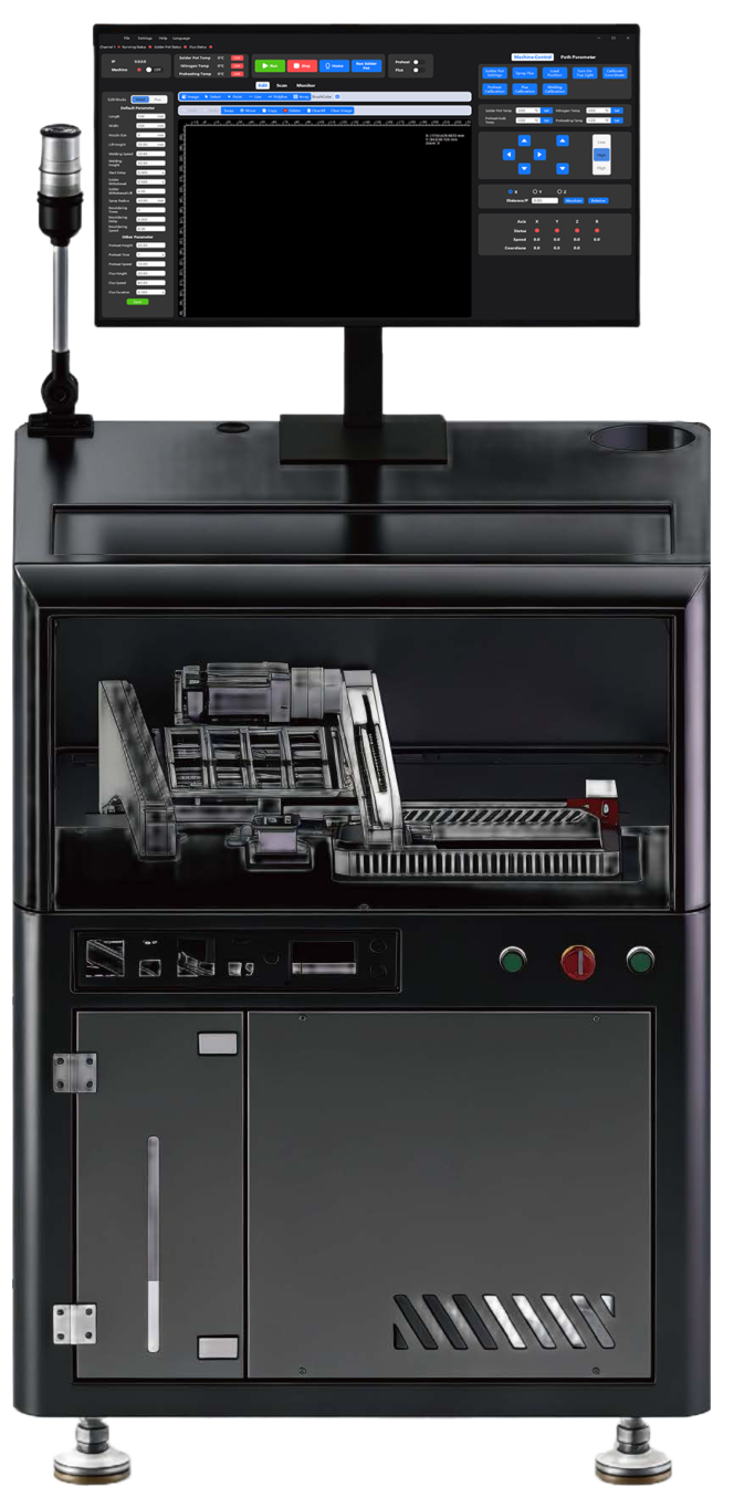
Welding module
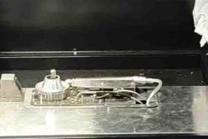
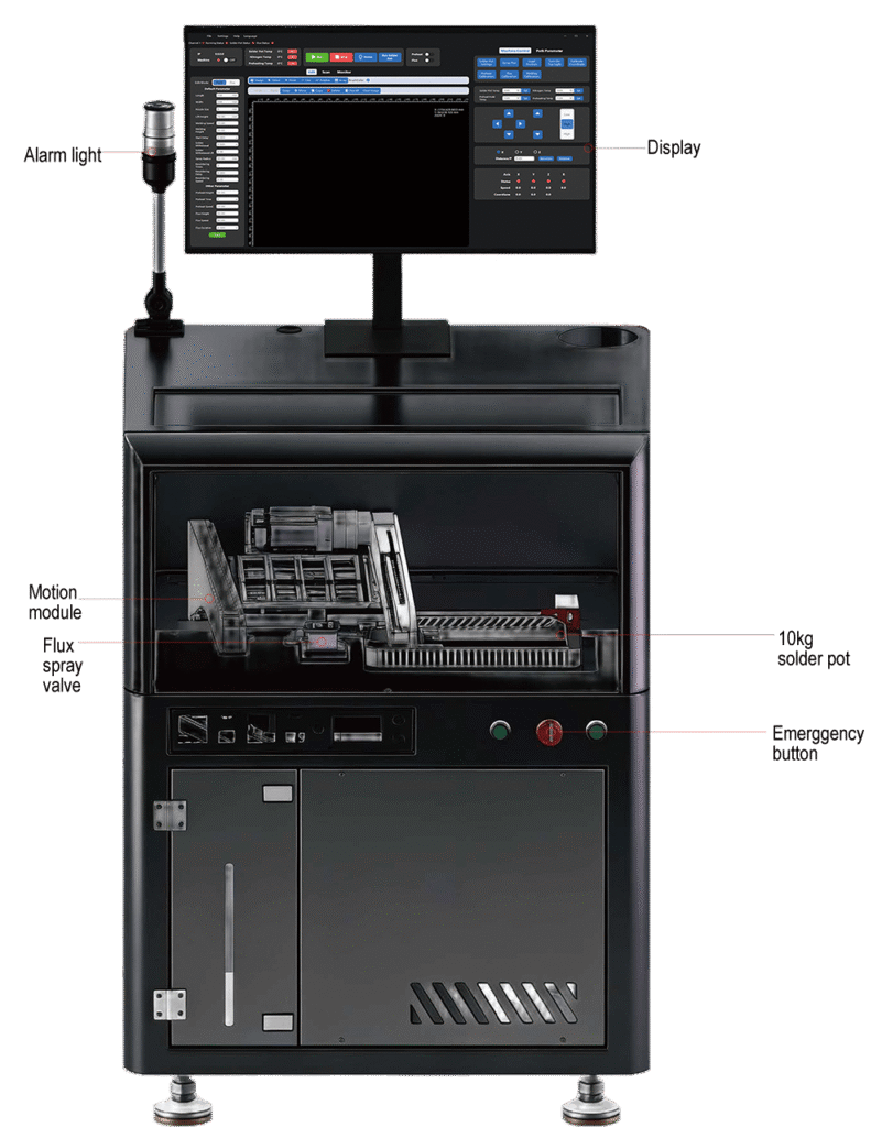
The soldering tin furnace is equipped with a mechanical pump and a nitrogen ring, as well as multiple sensors that enable detection of solder spray height, melted tin level in the tin furnace, and temperature of the tin furnace. Users can adjust and monitor various data in real-time through the software interface.
Software
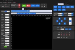
The self-developed system serves as the control hub of the entire
machine, enabling real-time startup, shutdown, and adjustment of
various module components through the operating system. Additionally, it facilitates no file visual scanning, allowing for more precise PCB soldering, editing of flux/weld paths, and reducing operational difficulty. Workers can quickly get started, achieving 3-minute programming.
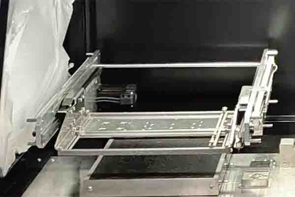
Motion module
The motion module’s X and Y axes are composed of belts and
servos, while the Z axis is composed of a lead screw and servo. The path is controlled by a self-developed system. The maximum moving speed can reach 500mm per second, and there is no shaking or deviation during transmission. The self-developed system can precisely control the motion path, ensuring it accurately reaches the predetermined welding, flux spraying, and preheating positions.
Flux spary module
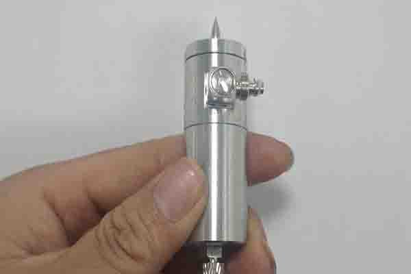
The flux spray valve chosen is a linear spray valve. Compared to
the spray valves used in other selective wave soldering processes,
the linear spray valve is more economical in flux usage. Due to its
focused spraying characteristics, it can precisely control the
movement and spraying action of the nozzle, ensuring that the flux evenly covers the soldering area, improving soldering reliability, and avoiding contamination of non-soldering areas.
Scan/monitor camera
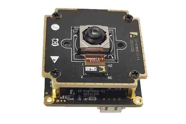
The scanning and monitoring camera equipped on the machine is
a 48-megapixel fixed-focus camera.
By utilizing a scanning camera in conjunction with our proprietary
scanning program, we can achieve visual scanning of PCB boards
without the need for files. Compared to the method of taking photos and uploading them for programming, visual scanning is not affected by lighting, angle, or phone pixel quality, resulting in high accuracy, fast speed, and zero errors.
The production monitoring camera, coupled with our proprietary
system, allows for real-time observation of the welding process,
facilitating a better understanding of the welding situation. T
SELF-DEVELOPED SYSTEM: VISUAL SCANNING AND DATA ENTRY
Main features: In the field of PCB board soldering production, efficient and precise soldering is the core to ensure product quality and production efficiency. Our self-developed system, leveraging three core functions, revolutionizes traditional soldering methods, injecting strong momentum into the production process and effectively sloving issues such as inaccurate positioning, cumbersome operation, and difficult
quality control in traditional selective wave soldering programming.
Feature 1:PCB board visual scanning without files: revolutionizing the traditional approach, achieving a leap in both efficiency and precision
Traditional selective wave soldering programming employs a photo upload method for positioning, which is not only cumbersome in operation, requiring manual adjustments of the
photo angle and position multiple times to ensure clear and usable images, but also often leads to positioning deviations due to factors such as lighting and angle, affecting subsequent
processing accuracy.
However,the PCB board visual scanning function equipped in our self-developed system has achieved a fundamental breakthrough in positioning methods. This function utilizes production camera scanning technology to quickly scan the entire PCB board and its detailed features such as dimensions, achieving precise positioning without manual intervention. Compared to the traditional method of taking photos and uploading, its positioning accuracy has been significantly improved, enabling it to accurately identify tiny components and circuit layouts on the PCB board, with positioning errors controlled to a very small range. The operation convenience has been greatly enhanced, eliminating tedious steps such as manual photo taking, uploading, and adjustment. Workers only need to place the PCB board in the designated area, and the scanning process will automatically start. The scanning speed has also achieved a qualitative leap, allowing for rapid scanning, significantly reducing the preparation time, saving valuable time for subsequent processing steps, and significantly improving overall production efficiency.
Feature 2 : Precise path editing: locking the welding point, ensure welding quality
After the visual scanning is completed, the path editing function of the self-developed system further enhances the processing accuracy. Based on the precise data obtained from visual scanning, the system edits the welding and auxiliary welding paths through points, lines, and line segments. Since the path editing is based on real and precise PCB board scanning information, the edited path can achieve precise positioning of the welding points.
During the welding process, the system strictly controls the operation of the welding equipment according to the edited path, ensuring that each welding point can be accurately identified and avoiding issues such as cold solder joint and incorrect soldering
caused by path deviation. Whether it is dense and tiny welding points or complex irregular circuit soldering requirements, the system can rely on precise path control to ensure the stability and consistency of soldering quality, laying a solid foundation for the reliable performance of PCB board products.
Feature 3:Real-time monitoring and calibration: ensuring production and quality through comprehensive control
The self-developed system boasts powerful real-time monitoring capabilities, enabling comprehensive real-time monitoring of the operating conditions of all relevant components of the main units, including the temperature of the soldering furnace, the height of solder spray, as well as the preheating plate and motion module. The system collects operating data from various components through high-precision sensors and displays it in real-time on the monitoring interface, allowing staff to know the operating
status at any time and promptly identify potential issues. More importantly, the system goes beyond mere monitoring and can also calibrate the parameters of relevant components according to soldering requirements through the self-developed system.
Selective Wave Soldering CBF09 Details
Hardware modules:
Motion board module – high-definition scanning camera – monitor camera
Main functionals:
Path editing – Parameter editing – Production-related – Calibration function
Production modules
Product scanning: Coordinate with the production scanning camera to quickly
scan the PCB board and generate a path editing diagram. Production monitoring: Monitor the production process in real-time, allowing for the inspection of welding path execution, real-time data of various parameters, etc
Calibration function module
It includes functions such as, flux calibration, welding calibration, and point
calibration, which are used to ensure the operational accuracy of various
Paths edit modules
Drawing tools: Provides drawing options such as, Point, Line, Polyline and Arrays. Path operations: Supports operations such as, modify the order, move, copy, Delete, and Clear paths, as well as Clear image and Clear preheating range. It also allows for the setting of the preheating range.
Selective wave soldering machine CBF09 data sheet
| Voltage: | AC 220V 50Hz | Total Power | 5000W |
| Tin Capacity: | 5kg (mini 3kg) | Warm-up Time | 30 minutes |
| Temp. Control Mode: | PID temperature control | Temp. Range | Room temp.~400℃ |
| Drive Mode: | Mechanical pump | Material: | Stainless steel |
| Furnace Size | 280*156*180mm | Warranty | 1 Year |
| Furance heating power | 1500W | Preheat power | Without preheat |
| Preheat power | Without preheat | Fixture dimensions | 180*240mm (adjustable) |
| Control Method | Motion control system+ computer control | Max. Soldering Area | 180x240mm (Customizable) |
| Flux Spray | Precise spraying with line spray valve | Programming Method | Visual scanning input, computer programming |
| Machine Dimention | 620*760*1576MM | Nitrogen amount requirements | ≥1.2M3/hour |
| Net Weight | 145KG | Nitrogen purity requirements | ≥99.998% |